
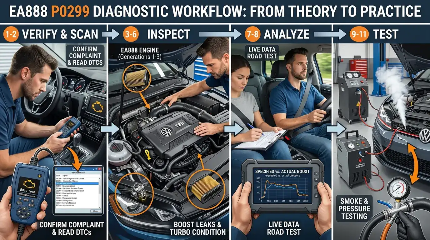
In Parts 1 and 2, we explored how the EA888 engine turbocharging system works and examined the most common causes of Diagnostic Trouble Code (DTC) P0299. In this part, we’ll move from theory to practice by following a professional diagnostic workflow. Rather than replacing parts based on guesswork, you’ll learn how to collect evidence using scan tools, live data, and systematic inspections to identify the true cause of an underboost condition.
Diagnose Before You Replace
One of the biggest mistakes DIY mechanics make is replacing the component they think is faulty before confirming the diagnosis. P0299 is a performance code, not a component code.
Unlike a fault indicating an open electrical circuit or a failed sensor, P0299 simply tells you that the engine failed to produce the boost pressure expected by the Engine Control Module (ECM). The ECM does not know whether the problem is a leaking hose, a sticking wastegate, a faulty diverter valve, a contaminated MAP sensor, or a worn turbocharger. It only knows that the measured boost pressure remained below the requested value for longer than its programmed threshold.
Professional technicians avoid unnecessary repairs by following a structured diagnostic process. Fortunately, enthusiasts can apply the same approach using readily available tools.
Step 1 – Verify the Complaint
Before connecting any diagnostic equipment, confirm the driver’s observations.
Ask questions such as:
- Does the vehicle consistently lack power?
- Does the problem occur only during hard acceleration?
- Has fuel economy changed?
- Does the EPC warning appear together with the Check Engine Light?
- Were any repairs performed recently?
- Has the vehicle been modified or tuned?
A P0299 that appeared immediately after replacing the turbocharger or intercooler often points toward an installation issue, such as a loose charge pipe or an improperly seated O-ring.
Understanding the history of the vehicle frequently saves hours of unnecessary testing.
Step 2 – Perform a Complete Vehicle Scan
Do not limit your diagnosis to P0299 alone.
Use a professional scan tool capable of reading Volkswagen and Audi manufacturer-specific information, such as:
- Ross-Tech VCDS
- ODIS Service
- OBDeleven
- ANCEL VD700
- Other advanced bidirectional scan tools
Record:
- All stored DTCs
- Pending DTCs
- Intermittent faults
- Freeze-frame data
Many technicians make the mistake of clearing codes immediately.
Don’t.
Freeze-frame information provides a snapshot of engine operating conditions when the fault occurred and may reveal valuable clues.
Why Freeze-Frame Data Matters
Freeze-frame data typically records information such as:
- Engine speed (RPM)
- Engine load
- Vehicle speed
- Coolant temperature
- Intake air temperature
- Boost pressure
- Throttle position
- Ambient pressure
For example, suppose P0299 occurs only at 4,200 RPM during heavy acceleration.
That immediately suggests a fault that becomes apparent only under high airflow demand, making a small boost leak or weak wastegate actuator more likely than a sensor problem.
Conversely, if the code appears during light throttle cruising, your diagnostic strategy may shift toward sensor faults or intermittent electrical issues.
Always save or photograph the freeze-frame information before clearing any codes.
Step 3 – Check for Additional Fault Codes
P0299 frequently appears alongside other diagnostic trouble codes.
These additional codes often help narrow the investigation.
Examples include:
- Diverter valve electrical faults
- Wastegate actuator position faults
- Boost pressure regulation faults
- MAP sensor performance codes
- PCV-related faults
- Misfire codes
- Airflow measurement faults
Do not assume every additional code is unrelated. Multiple DTCs often point toward the same underlying problem. For example, a boost leak may contribute to lean fuel trims, airflow discrepancies, and underboost simultaneously.
Step 4 – Perform a Visual Inspection
Before reaching for expensive diagnostic equipment, spend time performing a careful visual inspection.
Many P0299 faults are caused by issues that can be identified with basic hand tools and good lighting.
Inspect:
- Charge pipes
- Intercooler hoses
- Retaining clips
- Vacuum lines (where applicable)
- Turbo inlet hose
- Air filter housing
- Diverter valve connector
- MAP sensor connector
- Wastegate linkage
- Electrical harnesses
Look for:
- Loose clamps
- Cracked plastic pipes
- Oil residue around boost connections
- Broken retaining tabs
- Chafed wiring
- Signs of previous repairs
Oil staining around a boost connection often indicates escaping compressed air carrying a fine oil mist from the crankcase ventilation system. Although a light oil film is normal in turbocharged engines, concentrated deposits around a joint deserve further investigation.
Step 5 – Inspect the Air Intake System
An unrestricted air supply is essential for proper turbocharger performance.
Check:
- Air filter condition
- Turbo inlet pipe
- Aftermarket intake installations
A severely restricted air filter may reduce airflow enough to contribute to reduced boost, particularly at high engine loads. Although this is not among the most common causes of P0299, inspection requires only a few minutes and should never be overlooked.
Step 6 – Examine the Turbocharger
With the engine cool and safely accessible, inspect the turbocharger itself.
Look for:
- Oil leaks
- Damaged compressor housing
- Broken mounting hardware
- Loose heat shields
- Cracked turbine housing
If access allows, remove the intake pipe and inspect the compressor wheel.
Check for:
- Bent blades
- Foreign object damage
- Excessive oil deposits
- Shaft play
A very slight amount of radial movement is generally normal because the bearings ride on a film of pressurized engine oil during operation. However, excessive shaft movement or contact between the compressor blades and housing indicates significant wear. Do not condemn the turbocharger based solely on minor shaft movement without consulting factory specifications.
Step 7 – Verify Wastegate Movement
The wastegate should move smoothly throughout its operating range. Depending on your EA888 generation, inspection methods differ.
Vacuum-Operated Systems
Inspect:
- Vacuum hoses
- Actuator diaphragm
- Linkage movement
- Retaining clips
Using a handheld vacuum pump, verify that the actuator moves smoothly and holds vacuum without leakage. A leaking diaphragm or sticking linkage may prevent the wastegate from closing completely.
Electronic Wastegate Systems
For later EA888 engines equipped with electronic actuators:
Inspect:
- Electrical connector
- Wiring harness
- Linkage
- Actuator mounting bolts
Using VCDS or another compatible diagnostic tool, perform an actuator output test or observe commanded versus actual wastegate position if supported. Erratic movement, excessive noise, or position errors may indicate an actuator requiring further evaluation.
Remember that replacing an electronic actuator often requires a calibration or adaptation procedure before normal operation is restored.
Document Everything
Throughout the diagnostic process, record your observations. Professional technicians document:
- Fault codes
- Freeze-frame values
- Live data
- Test results
- Parts inspected
- Repairs performed
Keeping detailed notes prevents repeated testing and makes it much easier to recognize patterns if the fault returns later. For DIY enthusiasts, photographs of boost hoses, actuator positions, and scan tool readings can also be extremely valuable, especially when seeking advice from experienced technicians or online communities.
Step 8 – Analyze Live Data
After completing the visual inspection, the next step is to determine how the boost control system behaves while the engine is operating.
This is where a professional scan tool becomes invaluable. Whether you’re using Ross-Tech VCDS, ODIS, OBDeleven, ANCEL VD700, or another advanced scan tool, the goal is the same:
Compare the boost pressure requested by the ECM with the boost pressure actually produced by the engine.
Although menu names vary by scan tool, look for parameters similar to:
- Specified (Requested) Boost Pressure
- Actual Boost Pressure
- Wastegate Position
- Charge Pressure Control
- Throttle Position
- Engine Speed (RPM)
- Engine Load
- Intake Air Temperature
- MAP Sensor Pressure
Monitoring these values during a road test provides much more useful information than simply reading stored fault codes.
Performing a Safe Road Test
Choose a safe location where traffic conditions allow moderate acceleration without exceeding speed limits.
Ideally:
- Engine at normal operating temperature
- Air conditioning turned off (if practical)
- Flat roadway
- Minimal traffic
A common method is to accelerate steadily in third gear (or the equivalent gear in an automatic transmission) from approximately 2,000 RPM to 5,000 RPM while recording live data.
This operating range places the turbocharger under sufficient load to reveal most underboost problems.
Always obey local traffic laws and never attempt diagnostic testing in unsafe conditions.
Interpreting Requested vs. Actual Boost
Under normal operation, actual boost pressure should closely follow the requested boost pressure.
Small differences are expected as the turbocharger responds to changing engine load. However, if actual boost consistently lags behind the requested value during acceleration, the ECM interprets this as an inability to achieve its boost target.
Several patterns can help narrow the diagnosis:
Pattern 1 – Actual Boost Always Lower Than Requested
This often indicates:
- Boost leak
- Diverter valve leak
- Wastegate not fully closing
- Weak turbocharger
Pattern 2 – Boost Builds Slowly
Possible causes include:
- Wastegate sticking partially open
- Exhaust leak before the turbocharger
- Restricted intake
- Turbocharger wear
Pattern 3 – Boost Drops Suddenly
Possible causes include:
- Charge pipe separating under load
- Diverter valve opening unexpectedly
- Electronic wastegate malfunction
- Intermittent electrical connection
Rather than relying on a single reading, look for consistent trends throughout the data log.
Step 9 – Perform a Smoke Test
If live data suggests a boost leak but visual inspection reveals nothing obvious, a smoke test is one of the most effective diagnostic procedures available.
A smoke machine introduces low-pressure, non-toxic smoke into the intake system. Wherever smoke escapes, air can also escape under boost.
Common leak locations include:
- Charge pipe joints
- Intercooler end tanks
- Diverter valve seals
- Throttle body connections
- Vacuum fittings (where applicable)
- PCV system connections
Because many leaks open only under pressure, a smoke test frequently identifies faults that cannot be seen during a simple visual inspection.
For DIY enthusiasts, an affordable smoke machine can quickly pay for itself by preventing unnecessary parts replacement.
Step 10 – Pressure Test the Charge Air System
Some leaks appear only under higher pressure than a smoke test provides.
In these cases, a controlled pressure test may be helpful.
With the engine off, specialized adapters allow the charge air system to be pressurized using regulated compressed air.
Important: Never exceed the pressure recommended by the vehicle manufacturer or the testing equipment manufacturer. Excessive pressure can damage hoses, seals, or sensors.
Listen carefully for:
- Escaping air
- Whistling sounds
- Bubbling (if using a soap solution)
Pressure testing complements smoke testing and is particularly useful for locating very small leaks.
Step 11 – Verify Wastegate Operation
If no boost leaks are found, attention should return to the wastegate system.
For vacuum-operated systems:
- Confirm smooth actuator movement.
- Verify the actuator holds vacuum.
- Inspect linkage for excessive play.
- Check for corrosion or binding.
For electronic wastegate systems:
- Perform actuator output tests.
- Observe commanded and actual actuator positions.
- Verify successful adaptation after replacement.
- Inspect wiring for corrosion or damage.
A properly functioning wastegate should move smoothly and respond consistently to ECM commands.
Step 12 – Confirm the Repair
After replacing or repairing the faulty component:
- Reassemble all intake components carefully.
- Verify every hose clamp and retaining clip is fully seated.
- Clear diagnostic trouble codes.
- Perform another controlled road test.
- Compare requested and actual boost pressure again.
If the repair was successful:
- Requested and actual boost should closely track each other.
- Engine performance should return to normal.
- No fault codes should reappear after multiple drive cycles.
Avoid assuming the repair is complete simply because the Check Engine Light remains off immediately after clearing the code. Verification is an essential part of professional diagnostics.
Common Diagnostic Mistakes
Many unnecessary repairs result from avoidable errors. Among the most common are:
Replacing the Turbocharger Too Soon
Turbochargers are expensive. Always eliminate leaks, actuator problems, sensors, and control system faults first.
Ignoring Freeze-Frame Data
Freeze-frame information often indicates the operating conditions under which the fault occurred.
Failing to review it may lead to incorrect conclusions.
Skipping Live Data
Reading fault codes without analyzing live data provides only part of the picture. Live data frequently identifies whether the problem is mechanical or electronic.
Forgetting Adaptation Procedures
Many electronic wastegate actuators require adaptation after installation. Skipping this procedure may create new drivability problems.
Clearing Codes Too Early
Always record diagnostic information before clearing DTCs. Once erased, valuable evidence may be lost.
Preventive Maintenance
Although not every P0299 fault can be prevented, proper maintenance significantly reduces the likelihood of boost-related problems.
Recommended practices include:
- Replace the engine air filter at recommended intervals.
- Inspect charge pipes during routine maintenance.
- Check hose clamps after major engine repairs.
- Use the correct engine oil and change it on schedule.
- Allow the engine to reach operating temperature before heavy acceleration.
- Avoid immediately shutting off the engine after sustained high-load driving whenever practical, allowing turbocharger temperatures to stabilize.
- Address oil leaks promptly to reduce contamination of nearby components.
- Scan the vehicle periodically for pending fault codes, even if the Check Engine Light has not illuminated.
Preventive maintenance is generally far less expensive than repairing a neglected turbocharging system.
Frequently Asked Questions
Can I continue driving with P0299?
The vehicle will often remain drivable, but continued operation with reduced boost should not be ignored. Depending on the cause, performance may deteriorate further, and prolonged operation could contribute to additional component wear. Diagnose the problem as soon as practical.
Does P0299 always mean the turbocharger is bad?
No. In many cases, the root cause is a boost leak, diverter valve problem, wastegate issue, PCV fault, or another boost control component rather than the turbocharger itself.
Can a boost leak cause limp mode?
Yes. If the ECM determines that requested boost cannot be achieved, it may reduce engine power to protect the engine and turbocharger.
Can a bad PCV valve trigger P0299?
It can contribute.
A failed PCV system may create pressure imbalances or internal air leaks that affect boost regulation, particularly on certain EA888 engines.
Can I simply clear the code?
Clearing the code removes the warning but does not correct the underlying problem.
If the fault remains, the ECM will typically store P0299 again during subsequent driving.
Final Thoughts
Diagnostic Trouble Code P0299 is one of the most common turbocharger-related faults encountered on Volkswagen and Audi EA888 engines, but it is also one of the most frequently misdiagnosed.
The fault code itself does not identify the failed component. It simply tells you that the engine was unable to produce the boost pressure requested by the Engine Control Module.
Successful diagnosis requires a logical, evidence-based approach:
- Confirm the complaint.
- Scan the entire vehicle.
- Review freeze-frame data.
- Inspect the intake and boost system.
- Analyze live data.
- Perform smoke and pressure testing when necessary.
- Verify repairs before returning the vehicle to service.
Following this workflow minimizes unnecessary parts replacement and helps ensure the true cause of the underboost condition is identified.
Whether you’re an experienced technician or a dedicated automotive enthusiast, understanding how the EA888 boost control system operates will make diagnosing P0299 faster, more accurate, and far less expensive than relying on guesswork.
Related Articles on Akotex
To continue learning about EA888 diagnostics, be sure to explore these related guides:
- P334A Explained: Diagnosing Charge Pressure Actuator Electrical Malfunction
- How to Calibrate the IS12 Electronic Wastegate Actuator Using VCDS
- Choosing the Right Scan Tool: VCDS vs. OBDeleven vs. ANCEL VD700
Together, these resources provide a comprehensive foundation for diagnosing turbocharger and engine management issues across the EA888 platform.
Leave a Reply