
In this guide, I will show you how to perform IS12 wastegate actuator calibration and IS12 wastegate adaptation using VCDS. Proper IS12 wastegate actuator calibration is critical after replacing an IS12 turbocharger or electronic wastegate actuator on a Volkswagen EA888 Gen 3 engine.
I’ll walk you through every single step, no skipping, no jargon. For this job, I’m using VCDS to handle the adaptation. And if you’re sitting there wondering, “What is VCDS?”—you need to circle back and check out my earlier post: VCDS Scanner: The Most Important Tool I Used to Fix My Volkswagen EPC Light Issue (IS12 Turbocharger). Go read that first, then come right back here.
In my previous article, How I Diagnosed and Fixed My VW SportWagen IS12 Turbocharger After an EPC Light and Limp Mode Event, I explained how I diagnosed my Volkswagen Sportwagen and fixed it after an EPC light and turbocharger fault. During that repair, I discovered that proper wastegate actuator calibration and adaptation were essential for restoring reliable boost control. In this guide, I’ll walk you through the complete bench calibration process for the 06K145614G electronic wastegate actuator used on the IS12 turbocharger (06K145713L) found in many Volkswagen EA888 Gen 3 1.8T engines.
Why Wastegate Calibration Matters
Modern Volkswagen turbocharged engines rely on precise electronic boost control. Unlike older vacuum-operated systems, the IS12 turbocharger uses an Electronic Wastegate Actuator (EWGA) that communicates directly with the Engine Control Unit (ECU).
Because the actuator rod length is adjustable, every turbocharger installation requires proper calibration. Even a small adjustment error can cause:
- EPC warning lights
- P0299 underboost faults
- P00AF wastegate faults
- Poor acceleration
- Limp mode activation
- Reduced turbocharger efficiency
Consequently, calibration is not optional—it is a critical step in ensuring proper turbocharger operation.
Understanding the IS12 Wastegate Components
The IS12 turbocharger controls boost pressure using a wastegate flapper located inside the turbine housing.
Several components work together to control this flapper:
Actuator Rod
Connects the electronic actuator to the wastegate lever.
Lock Nut (10 mm)
Locks the actuator rod adjustment in place after calibration.
Rod End (Clevis)
Attaches the actuator rod to the wastegate lever while allowing movement.
Wastegate Lever
Transfers actuator motion directly to the wastegate flapper.
Wastegate Flapper
Opens and closes the exhaust bypass path to regulate boost pressure.
Actuator Bracket
Secures the electronic actuator to the turbocharger housing.
Since rod length directly affects wastegate position sensor voltage, accurate adjustment is essential.

Major components of the IS12 electronic wastegate system including the actuator rod, lock nut, clevis, wastegate lever, and actuator bracket.
How the Electronic Wastegate System Works
The ECU continuously monitors engine load, throttle position, air mass, and boost pressure. Based on these inputs, it sends Pulse Width Modulated (PWM) signals to the electronic wastegate actuator.
When More Boost Is Required
The actuator retracts the rod, causing the Wastegate flapper to close. As a result, more exhaust gas flows through the turbine wheel, increasing turbocharger speed and boost pressure.
When Less Boost Is Required
The actuator extends the rod, opening the wastegate flapper. Consequently, some exhaust gases bypass the turbine wheel, reducing boost pressure.
At the same time, an internal position sensor continuously reports actuator position back to the ECU using a voltage signal.
Understanding Wastegate Actuator Voltage Feedback
The electronic actuator contains a built-in potentiometer that provides position feedback to the ECU.
For a properly calibrated IS12 turbocharger:
- Target fully closed-position voltage: approximately 3.5–3.9 V (3.5x V ideal based on my experience).
The ECU uses this voltage as a reference point for all future wastegate movements.
Therefore, even if the wastegate mechanically appears correct, incorrect voltage feedback can still cause fault codes and boost control issues.
What Is Wastegate Actuator Bench Calibration?
Calibration is the mechanical process of adjusting the actuator rod length.
The goal is simple:
When the wastegate flapper is fully seated against its stop, the position sensor should report a voltage between 3.5V and 3.9V.
By adjusting the rod length, you ensure that the ECU receives accurate feedback regarding wastegate position.
What Happens If Calibration Is Incorrect?
If the actuator rod is too short:
- Excessive preload occurs
- Mechanical stress increases
- Adaptation may fail
If the actuator rod is too long:
- The wastegate may not fully close
- Boost leaks may develop
- Underboost faults may occur
In either case, the ECU may trigger:
- P0299 Underboost
- P00AF Turbocharger/Supercharger Boost Control Fault
- EPC Light
- Limp Mode
What Is Wastegate Adaptation?
Adaptation is the electronic learning process performed using diagnostic software such as VCDS.
During adaptation, the ECU:
- Commands the actuator to move to the closed position.
- Reads the actual voltage feedback.
- Stores that voltage as its learned reference value.
- Uses the reference to calculate all future wastegate positions.
Without adaptation, the ECU cannot accurately control boost pressure even if calibration was performed correctly.
Calibration vs Adaptation
Process
Type
Purpose
Calibration
Mechanical
Sets correct actuator rod length (Calibration sets the voltage mechanically)
Adaptation
Electronic
Teaches ECU the actual closed position voltage
Both procedures must be completed for proper operation.
Tools Required for Bench calibration and Adaptation
Before beginning, gather the following tools:
10 mm wrench

VCDS diagnostic interface

Six-pin wastegate actuator extension harness

Battery charger

Digital multimeter

Important: Verify Battery Voltage First
Before starting calibration:
- Fully charge the battery. Verify the battery voltage exceeds 13 volts. During my adaptation, I used a multimeter, but VCDS software can measure the voltage also. See the picture below.


Low battery voltage, even 12 volts, can cause:
- Erratic actuator movement
- Communication errors
- Failed adaptation procedures
- Incorrect voltage readings
A stable power supply dramatically improves calibration accuracy.
IS12 Bench Calibration Procedure Using VCDS
Step 1: Connect the Actuator
With the turbocharger removed from the vehicle:
- Attach the actuator to the turbo and attach the actuator rod to the Clevis but don’t tighten the 10 mm lock nut.
- Ensure ignition is OFF then connect the actuator electrically to the vehicle harness using the 6 pins extension harness. The harness will allow you to work on the turbo while it is outside of the engine. Connecting the actuator while the car is ON may trigger fault codes or damage electrical connectors.
- Turn ignition ON without starting the engine.
You should hear the actuator cycling or buzzing.
Step 2: Monitor Wastegate Voltage
Open VCDS Software

Click on [Options]

> [Test]

This is to make sure that the VCDS interface is communicating with the software.
[OK] > [Save]
> [Select]

>[01-Engine]

[Advanced Measuring Values]

Type IDE05312 in the search field then select it for monitoring

Monitor:
- IDE05312 displays the voltage signal reported by the electronic wastegate actuator position sensor. This is the value used during calibration.
Record the voltage value.
Step 3: Simulate Fully Closed Wastegate Position
This is the most important step.
- Loosen the 10 mm lock nut.
- Manually force the wastegate flapper completely closed.
- While holding the flapper closed, adjust rod length.
Adjustment effects:
- Clockwise rotation looking at the Clevis = increases voltage
- Counterclockwise rotation looking at the Clevis = decreases voltage
Make adjustments in small increments.
Target fully closed-position voltage: approximately 3.5–3.9 V (3.5x V ideal based on my experience).
Step 4: Run Wastegate Adaptation
In VCDS go to:
[01-Engine]

[Basic Settings]

Select [IDE04304 Initial Adaptation of charge-air pressure actuator] from the drop down menu


Click on [Go] and start the procedure.
The actuator will cycle through several positions. This process took me barely 4 seconds when I adapted my turbo.

If adaptation aborts, recheck the battery voltage and adjust the rod length before trying again.
Step 5: Verify Results
After successful adaptation:
- Cycle ignition OFF.
- Turn ignition ON.
- Recheck voltage values.
- Tighten the lock nut securely.
- Run adaptation one final time.
- Although the actuator was adapted during bench calibration, performing adaptation again after installation ensures the ECU learns the actuator position under final installed conditions.
Best Practices for Reliable Results
To achieve long-term reliability:
Perform calibration before adaptation.
Maintain battery voltage above 13 volts.
Make small rod adjustments.
Monitor live voltage data continuously.
Securely tighten the lock nut after adjustment.
Clear all fault codes before testing.
Verify boost pressure during the final road test.
Proper IS12 wastegate actuator calibration and adaptation can mean the difference between a reliable turbocharger and recurring EPC lights, limp mode events, and frustrating fault codes. Although the procedure requires patience and careful adjustment, it ensures that the ECU receives accurate position feedback and maintains precise boost control.
When I completed this process on my Volkswagen SportWagen, it permanently resolved the boost control issues that had triggered my EPC light and limp mode. If you’re replacing an IS12 turbocharger or electronic wastegate actuator, take the time to perform calibration and adaptation correctly—you’ll save yourself countless hours of troubleshooting later.
Have You Calibrated an IS12 Wastegate Actuator?
Share your experiences, challenges, or questions in the comments below. Your feedback may help other Volkswagen owners avoid costly mistakes and get their EA888 turbocharger running perfectly again.
Blog
This section provides an overview of the blog, showcasing a variety of articles, insights, and resources to inform and inspire readers.
EA888 Gen 3 Water Pump Explained: How It Works, Failure Points and Diagnosis
If you own a Volkswagen or Audi with an EA888 Gen 3 1.8T or 2.0T…

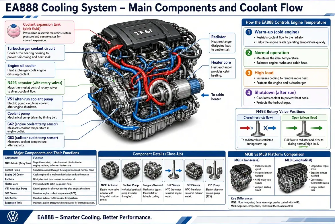

EA888 Cooling System Explained: How Volkswagen Controls Engine Temperature
Detailed technical illustration of the EA888 Gen 3 engine showing main cooling system components with…
VCDS Part 1-4: How to Perform Your First Auto-Scan on a Volkswagen or Audi
If you have completed the first three articles in this VCDS series, you now understand…


Leave a Reply