
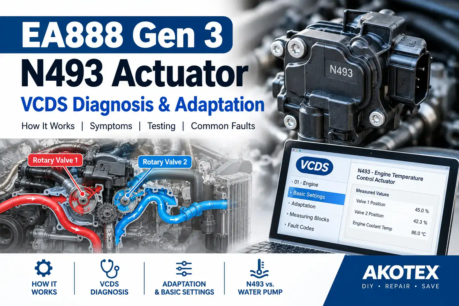
Rotary Valve, VCDS Diagnosis & Adaptation
The N493 Engine Temperature Control Actuator ranks among the most important—and most misunderstood—components in the cooling system of many Volkswagen and Audi EA888 Gen 3 engines.
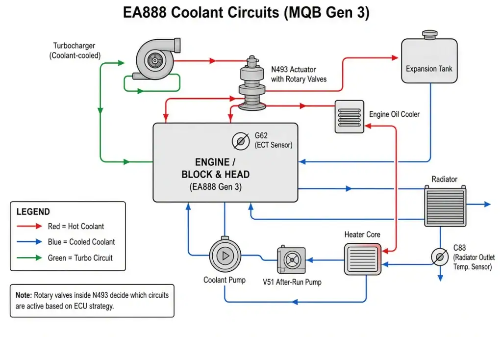
Unlike a conventional thermostat that simply opens as coolant temperature rises, the EA888 Gen 3 Innovative Thermal Management (ITM) system can actively control coolant routing. It does this with two mechanically coupled rotary slide valves. In turn, the N493 actuator positions those valves according to commands from the engine control module (ECM). As a result, the engine can manage warm-up and operating temperature more precisely. In addition, this design supports more precise thermal strategies under varying loads.
Here is the key distinction: the water pump creates coolant circulation. Meanwhile, N493 controls where that coolant goes.
That distinction becomes extremely useful when diagnosing overheating, slow warm-up, temperature-control faults, or cooling-system DTCs.
This article explains how N493 works, what can fail, how to diagnose it with VCDS, and what Basic Settings or adaptation actually does. It also shows how to distinguish an N493 problem from a water-pump, sensor, wiring, or related cooling-system fault.
Important: Not every EA888 engine variant uses exactly the same cooling architecture. Always verify the system against your engine code, vehicle, VIN, and factory service information.
What Is the N493 Engine Temperature Control Actuator?
N493 is the Engine Temperature Control Actuator used in the EA888 Gen 3 thermal-management system.
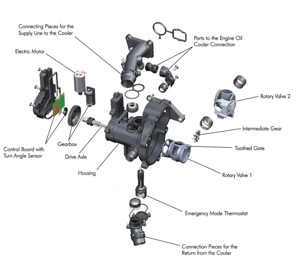
It is an electrically operated actuator mounted as part of the cooling-system assembly. Inside, the actuator contains an electric motor, gearing, and position-sensing components. Consequently, it moves the rotary valves to control coolant flow through different parts of the engine cooling circuit.
Volkswagen and Audi training material describes the system as using two mechanically coupled rotary slide valves. Their angular position is controlled according to engine operating maps stored in the ECM.
The basic control loop works like this: ECM command → N493 electric motor → reduction gearing → rotary valves → position feedback → ECM.
This matters because N493 is not simply an electrically controlled version of a traditional thermostat. Instead, the ECM can request different valve positions depending on factors such as engine temperature, load, and operating conditions. The result is a variable coolant-routing system rather than a simple open/closed thermostat.
How the N493 Rotary Valves Work
The N493 assembly controls two rotary slide valves. Although the two valves are mechanically coupled, they do not simply behave as one conventional valve.
Rotary valve 1
Rotary valve 1 is directly driven by the N493 actuator through its shaft. It participates in controlling coolant flow involving circuits such as the main radiator, engine oil cooler, and engine cooling circuit.
Rotary valve 2
Rotary valve 2 is mechanically linked to rotary valve 1 through an intermediate gear arrangement. Its movement changes coolant flow through the engine block circuit.
Thanks to the relationship between the two valves, the ECM can establish different thermal-management states rather than relying on a single thermostat opening point.
Factory training information describes the rotary valves as being mechanically coupled and controlled according to maps stored in the ECM. In practice, the system can achieve variable engine temperatures in the approximate 85–107 °C range, depending on operating conditions and application. For this reason, the system is often called Innovative Thermal Management (ITM).
Why Volkswagen Used Rotary Valves
The objective is not simply to keep the engine as cold as possible. During a cold start, the engine benefits from reaching its operating temperature efficiently. Once the engine is warm, however, the cooling system needs to remove enough heat to maintain the desired temperature under the current load.
A variable coolant-routing system allows the ECM to manage these competing requirements. During warm-up, coolant flow can be managed to reduce unnecessary heat loss. As temperature and load increase, the rotary valves can progressively change coolant routing and increase heat rejection through the radiator and other circuits.
Volkswagen and Audi documentation describes this system as being designed for rapid engine warm-up and thermodynamically optimized temperature regulation. Therefore, a problem with N493 can produce symptoms that look very different depending on where the valves become stuck or how the actuator fails.
N493 vs. the Water Pump
This is one of the most important distinctions when diagnosing the EA888 cooling system. In particular, confusing the two components often leads to unnecessary replacements.
Water pump role
The pump provides the force that circulates coolant through the cooling system.
N493 role
N493 controls coolant routing by positioning the rotary valves.
Think of the system like plumbing. The water pump creates flow, while N493 controls the routing of that flow.
A working water pump cannot compensate for a rotary valve that is incorrectly positioned. Likewise, a correctly functioning N493 cannot compensate for a pump that cannot circulate coolant properly.
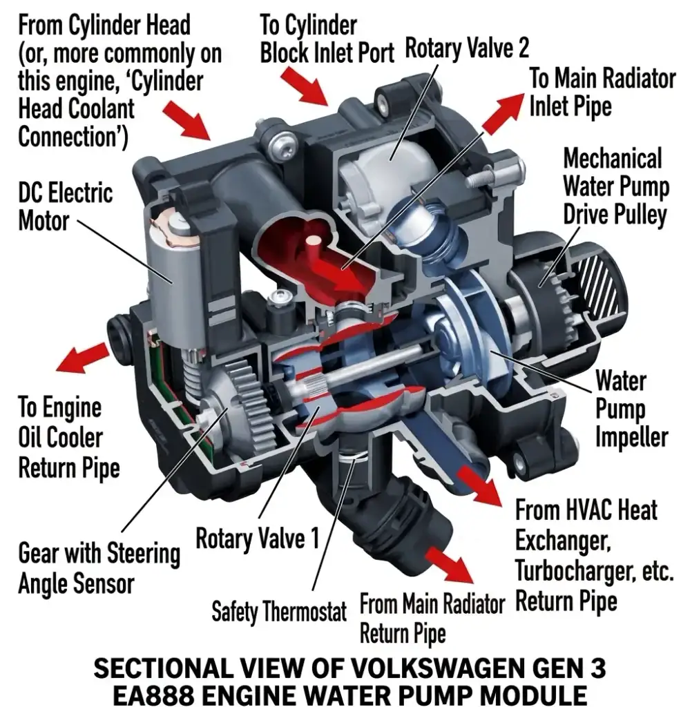
The exact pump drive arrangement varies between EA888 applications. On the EA888 Gen 3 architecture described in Volkswagen and Audi training material, the coolant pump is mechanically driven by a toothed belt associated with the balance-shaft drive. Other EA888 generations and applications should not automatically be assumed to use the same arrangement.
For this reason, diagnosing the entire cooling system is more useful than replacing whichever component happens to be easiest to blame.
What Can Fail Inside N493?
Several different failures can produce similar symptoms. Below are the main modes.
1. Electric motor failure
The actuator motor may fail electrically or mechanically. In that case, the ECM can request a valve position, but the actuator may not move.
2. Gear mechanism failure
Sometimes the motor operates while the internal gearing fails to transmit movement correctly to the rotary valves.
3. Position-feedback failure
N493 uses position feedback so the ECM can determine where the actuator and valve mechanism is positioned. A feedback problem can create a situation where the ECM commands movement but the reported position is implausible.
4. Mechanical restriction
The rotary valve mechanism itself can become difficult to move or fail to reach the commanded position. This can result in a difference between specified and actual position.
5. Wiring or connector problems
A damaged connector, poor electrical connection, damaged wiring, or corrosion can prevent the actuator from responding correctly. Do not assume an actuator is defective until the electrical circuit has been checked.
As a quick multimeter check, ALLDATA documents a factory specification for N493 resistance. Between connector pins 4 and 5 the reading should be 2.4–4.6 Ω. An open circuit, short, or value well outside this range supports an electrical fault in the actuator or its wiring. In one documented ALLDATA case, measured resistance of 0 Ω (a dead short) confirmed a failed actuator, and replacement resolved the fault.
6. Internal sealing or coolant leakage
The N493 assembly contains coolant-side sealing components. Factory service procedures specifically call for renewing seals and O-rings when the actuator is removed.
If you find coolant residue, moisture, discoloration, or dried coolant deposits around the actuator or electrical connector, investigate the actuator and its sealing condition carefully. In particular, coolant residue inside the electrical connector is a serious physical clue. Do not treat that as merely an electrical problem.
Symptoms of an N493 Problem
Depending on the failure mode, symptoms can include the following:
- Engine temperature that does not behave normally
- Slow or abnormal warm-up
- Cooling-system warning or MIL
- Incorrect temperature behavior under different loads
- Reduced heater performance
- Cooling-system DTCs
- Implausible coolant-temperature readings
- Specified and actual actuator position disagreement
- N493 adaptation or basic-setting failure
- Electrical or communication faults associated with the actuator system
The important point is that these symptoms are not unique to N493. A water-pump problem, coolant-temperature sensor problem, wiring fault, trapped air, leak, thermostat-related issue, or another cooling-system problem can produce overlapping symptoms.
Cooling-System DTCs Relevant to N493 Diagnosis
A diagnostic code should be treated as evidence about a system—not as an automatic instruction to replace a component. Therefore, always combine codes with live data and physical inspection.
| DTC | What it indicates | Relevance to N493 diagnosis |
| P00B7 | Coolant-flow/performance problem | Can involve N493, the coolant pump, wiring, trapped air, or another cooling-system problem |
| P2181 | Cooling-system performance malfunction | Investigate temperature regulation and whether coolant is being routed correctly after warm-up |
| P2183 | Coolant Temperature Sensor 2/G83 range-performance problem | Investigate G83 and its circuit; abnormal thermal regulation can also make this relevant to N493 diagnosis |
| P2681 | Coolant bypass-valve control circuit/open | Vehicle-specific; may involve N82/GX33 rather than N493 |
| U-codes | Communication/control-system faults | Identify the affected module and determine whether the communication problem is related to the cooling system |
P2181 deserves special attention
Ross-Tech describes P2181 as a Performance Malfunction in Cooling System. The code can set when coolant temperature remains lower than expected for the operating conditions. One example is a thermostat that opens and remains open, allowing coolant temperature to fall below the expected operating range.
On an EA888 Gen 3 using N493 thermal management, this makes the rotary-valve system worth investigating. For example, if the engine warms normally but the coolant temperature subsequently falls when it should remain within the expected operating range, ask whether N493 is failing to restrict or route coolant as commanded.
Do not, however, treat P2181 alone as proof that N493 has failed. Verify the actual coolant temperatures, sensor signals, actuator behavior, and other cooling-system components.
P2183 does not automatically mean N493
P2183 is associated with Coolant Temperature Sensor 2, commonly identified with the radiator outlet temperature sensor G83 in relevant applications. That makes it important not to label P2183 as an N493 fault. Instead, use it as a clue.
If the radiator outlet temperature is implausible, investigate G83, its wiring, connector condition, actual radiator temperature, temperature difference across the radiator, N493 coolant routing, and other cooling-system components.
A malfunctioning thermal-management system can create unusual temperature differences that make a sensor-related DTC appear. The correct diagnostic question is therefore not “P2183 means I need an N493.” Rather, ask why the coolant temperature information is becoming implausible.
P2681 is not simply an N493 code
P2681 requires particular caution. Ross-Tech identifies it as a Control Circuit for Coolant Bypass Valve. Possible causes include wiring to the Coolant Shut-Off Valve N82 and problems involving the Engine Temperature Control Module GX33.
Therefore, a P2681 should not automatically be described as an N493 failure. That said, technical articles on EA888 Gen 3 electronic water-pump and thermostat-assembly failures note that P2681 can appear alongside N493-related faults and codes such as P2556. When P2681 is present, the N493 assembly and its integrated components should still be examined as part of the diagnostic process—not because P2681 is an N493 code, but because the components may share a physical assembly or related electrical circuit.
The exact components involved depend on the vehicle and cooling-system implementation. When P2681 appears, follow these steps:
- Start by identifying the exact vehicle and ECU.
- Next, note the component named by the diagnostic system.
- Then check the associated wiring and connector.
- Afterwards determine whether N82, GX33, N493, or another cooling-system component is actually involved.
- Finally use live data to determine what the system is commanding and what is actually happening.
This distinction prevents unnecessary parts replacement.
Diagnosing N493 with VCDS
VCDS is particularly useful because an N493 diagnosis should go beyond simply reading fault codes. For this reason, begin with VCDS → Auto-Scan → Engine Control Module → Fault Codes.
Record the DTC, fault frequency, freeze-frame information, coolant temperature, engine speed, engine load, and any associated actuator or sensor information. Then move to Advanced Measuring Values.
Search for labels associated with engine temperature regulation, N493, temperature control actuator, coolant temperature, radiator outlet temperature, actuator position, specified position, actual position, adaptation, and cooling-system operation. Keep in mind that the exact measuring-value labels and identifiers depend on the ECU software and vehicle application.
Do not rely on an IDE number alone
Some online diagnostic articles mix measuring values from different systems or different ECU applications. Rather than assuming that a particular IDE identifier belongs to N493, verify the actual measuring-value label displayed by your specific ECU.
If an online guide gives you an IDE number, compare its actual VCDS label and description with what your vehicle reports. The label is more useful than blindly copying an identifier from another vehicle.
The Most Important VCDS Test: Specified vs. Actual
If your ECU provides both commanded and actual N493 position information, this can be one of the most useful diagnostic observations. In practice, the comparison quickly reveals whether the actuator is responding.
The ECM requests a position. N493 then moves. The position sensor reports the resulting position. Finally, the ECM compares what it requested with what it sees.
Conceptually the loop is: Specified position → N493 → Actual position.
If the specified position changes but the actual position does not move, moves very slowly, stops at one point, remains substantially different, becomes implausible, or changes intermittently, further investigation is warranted.
Possible causes include the N493 motor, internal gearing, rotary valve restriction, position sensor, wiring, connector, or a mechanical installation problem. A mismatch does not automatically prove that the actuator itself is defective.
N493 Basic Settings and Adaptation
After replacing N493, adaptation is an important part of the repair on applications that support it. Factory service information for EA888 Gen 3 applications specifically instructs technicians to perform adaptation of the N493 actuator after replacement. Some service procedures access this through the vehicle diagnostic tester’s Guided Functions, while other applications expose the function through Basic Settings.
The purpose is essentially to establish or verify the relationship between actuator movement and position feedback. Depending on the ECU, the procedure may command the actuator through part or all of its usable range and evaluate the position feedback.
An important limitation
Not every EA888 Gen 3 ECU or application necessarily exposes the same N493 adaptation function. Do not assume that every vehicle will have an identically named Basic Setting, group number, temperature requirement, or operating time.
When your ECU provides an N493 adaptation routine, follow the procedure specified for that vehicle and ECU. Should the menu option be missing, that absence by itself does not prove that the actuator is defective. Instead, use the measuring values available in that ECU.
Monitor specified position, actual position, coolant temperatures, radiator outlet temperature, related cooling-system status, and stored DTCs. A commonly used diagnostic comparison is the deviation between requested and actual position. Multiple independent diagnostic sources reference approximately ±5° as a practical threshold between specified and actual angle. Treat that as application-specific diagnostic guidance rather than a universal EA888 specification.
What Does a Failed Adaptation Tell You?
A failed adaptation is a useful clue, but it is not automatically proof of a defective new N493. Instead, treat it as a signal to dig deeper into the supporting system.
Successful adaptation supports the conclusion that the actuator can move, position feedback is plausible, the ECM can communicate with the actuator, and the mechanism can reach the required positions.
When adaptation fails or aborts, investigate the following points:
- Correct actuator part
- Connector condition
- Wiring integrity
- Battery voltage
- Mechanical installation
- Rotary-valve movement
- Coolant-system condition
- Position feedback
- ECU-specific adaptation requirements
Only after those checks should you conclude that the replacement actuator itself is defective.
What About the Emergency Thermostat?
The rotary-valve system also incorporates a fail-safe or emergency thermostat. This provides a mechanical safety function if the active thermal-management system cannot operate normally. Consequently, the design retains a mechanical backup even when electronic control is lost.
Volkswagen and Audi training documentation describes an expansion-element thermostat serving as a safety device. In the documented architecture it opens at approximately 113 °C in the event of a failure. This is important because the N493 system is not relying exclusively on electronic control for every possible failure condition. Still, the exact design should be verified for the specific engine variant.
Water Pump and N493: A Practical Diagnostic Comparison
Use the table below to organize evidence. It is not a replacement for diagnosis.
| Observation | N493 suspicion | Water-pump suspicion |
| Specified/actual N493 position disagreement | High | Low |
| N493 adaptation failure | High | Low |
| Actuator electrical fault | High | Low |
| Damaged N493 connector | High | Low |
| No detectable coolant circulation | Possible | High |
| Pump mechanical noise or leak | Low | High |
| Cooling temperature abnormality | Possible | Possible |
| P2181 | Possible | Possible |
| P2183 | Possible indirectly | Possible indirectly |
| P2681 | Application-dependent | Application-dependent |
Replacing N493: What to Verify
Before installing a replacement actuator, verify the exact part against the vehicle. EA888 cooling-system components exist with numerous suffix revisions. Part-number families can include suffixes such as B, E, F, G, H, J, K, L and M, depending on the component and application. For this reason, part matching must be done carefully.
Do not assume that matching the basic 06L part-number family means two parts are interchangeable. Always verify VIN, engine code, model year, cooling-system configuration, supersession information, factory parts catalog, and applicable service documentation. A suffix change can represent a revision, a supersession, or a different application.
After Replacing N493
The repair does not end when the actuator is bolted back onto the engine. Factory service information specifies replacing the relevant seals and O-rings during removal and following the vehicle-specific coolant filling procedure. It also calls for N493 adaptation after replacement on applicable systems.
A practical sequence is as follows:
- Verify the replacement part. Confirm the actuator is correct for the VIN and engine.
- Install new seals. Do not reuse sealing components that the service procedure specifies replacing.
- Reassemble the cooling system. Make sure every coolant connection is correctly seated. A factory service procedure specifically warns that an incorrectly seated connection can leak.
- Refill the cooling system. Use the coolant and filling procedure specified for the vehicle. Do not assume every EA888 application uses the same bleeding procedure.
- Perform N493 adaptation. If the ECU provides the appropriate adaptation or Basic Settings function, perform it according to the applicable procedure.
- Clear stored DTCs after the repair is complete.
- Rescan the vehicle. Run another scan and determine whether the original fault returns.
- Monitor live data. Compare actuator position, coolant temperature, and radiator outlet temperature where available.
- Check for leaks. Inspect the N493 area and all disturbed coolant connections.
- Recheck coolant level. After the engine has completed the appropriate warm-up and cool-down cycle, verify the coolant level according to the vehicle’s procedure.
A Practical N493 Diagnostic Workflow
If your EA888 Gen 3 develops a cooling-system fault, avoid immediately ordering a pump or N493. Instead, follow a structured sequence that separates symptoms from root causes:
- Scan the vehicle. Perform a complete VCDS Auto-Scan.
- Record the DTCs. Do not erase them before recording freeze-frame and fault information.
- Identify the cooling-system architecture. Confirm that your engine actually uses the N493 rotary-valve system.
- Inspect the physical system. Look for coolant leaks, damaged connectors, corrosion, dried coolant residue, damaged wiring, and poorly seated coolant connections.
- Check coolant level and condition. A low coolant level or air in the system can create misleading symptoms.
- Check temperature data. Compare engine coolant temperature with radiator outlet temperature and other available temperature measurements.
- Check N493 position data. If available, compare specified and actual actuator position.
- Test adaptation. If the ECU provides an N493 adaptation function, perform it according to the applicable procedure.
- Investigate the water pump separately. Do not condemn the pump simply because the cooling system has a fault.
- Rescan. After repair, clear faults and verify that they do not return.
- Confirm the physical result. The final test is not simply that the code disappeared. The cooling system should behave correctly under real operating conditions.
Don’t Diagnose the Cooling System by Temperature Gauge Alone
The dashboard temperature gauge is useful, but it is not a substitute for diagnostic data. Modern engine management systems continuously monitor coolant temperature and use multiple inputs to control thermal management. In other words, the gauge alone rarely reveals the full picture.
Two vehicles can show a similar dashboard temperature while having very different coolant behavior. With VCDS, you can often see information that the dashboard does not show. That makes live data particularly valuable when diagnosing N493.
For example, if the engine reaches operating temperature but the radiator outlet temperature suddenly behaves abnormally, that information can help distinguish a sensor problem from a coolant-routing problem. The goal is to understand what the ECM requested, what the actuator did, and what temperatures resulted.
Final Takeaway
The N493 Engine Temperature Control Actuator is not simply another thermostat. It is an electronically controlled actuator that positions two mechanically coupled rotary valves to manage coolant routing in the EA888 Gen 3 Innovative Thermal Management system.
The most useful mental model is: Water pump = circulation. N493 = coolant routing. ECM = control strategy. Position sensor = feedback.
When diagnosing an N493 problem, do not rely on a single DTC or a single symptom. Instead, use the complete picture: fault codes, freeze-frame, physical inspection, coolant temperatures, specified versus actual actuator position, adaptation results, and cooling-system behavior.
Also remember that not every EA888 Gen 3 vehicle exposes exactly the same measuring values or adaptation functions. The ECU software, engine code, vehicle application, and cooling-system architecture matter.
That is why the safest approach is not to memorize one VCDS measuring-value number or one Basic Settings procedure. Instead, learn to follow the control loop: ECM command → N493 movement → valve position → coolant routing → temperature response.
Once you understand that chain, N493 diagnosis becomes much more logical. As a result, you are far less likely to replace an expensive component without proving that it is actually the source of the problem.

Leave a Reply